| Author |
Message |
Stephen B
Samba Member

Joined: November 03, 2013
Posts: 53
Location: Victoria, BC, Canada

|
 Posted: Thu Feb 04, 2016 2:04 am Post subject: Re: 1968 Type 1 - My First Resto Posted: Thu Feb 04, 2016 2:04 am Post subject: Re: 1968 Type 1 - My First Resto |
 |
|
| Wow, what an amazing job you have done. I too am into the last days of my restore of a VW Blue 1968 bug. I got mine in October 2013 and have done everything I could, apart from taking the body off the frame. Luckily, I found a gem. No bubble rust on the car anywhere. It had original paint, seats, etc. I have shined every nut and bolt, finding parts for the car from all over the world, and doing it all in my driveway. I took the engine out, and put it back after rebuilding it. Its the original stock motor to the car. A single port 1500. The serial number matches the car's age. The door locks and the ignition are the same key. I was getting so close last year, and as suck, this winter I did break down and stored it in a friends garage, so I could work on it during bitter cold and wet days. I never have done a restore previous to now, despite this being my 10th bug I have owned. My problems had really started when I finally decided to built a correct, stock beetle. There were so many parts in the car that disappeared in the years. So many things rigged up, rather than do it right. I could count the very few aftermarket parts on this car in a second. I was even able to get the cardboard for the front hood from an original 68 bug, and the little cable that connects the thermostat to the air cleaner flap that forces more warm air into the carb. Its been hard, but I love doing it too. My wife really loves the car as well, and we cant wait to show it off and drive it. So I know your long days thinking about nothing but the car, wondering if you could figure out where all the things go back in, after stripping it down to just a shell. Interestingly enough, when I pulled back the small original piece of headliner that was left just above the driver side of the car, there was a handwritten "68" marked on the roof, surely done in the factory in Germany when the car was made. So I cleaned, sanded, primed, and painted around that number, and then put the new headliner in. If ever anyone takes it out again, they will see the treasure from Wolfsburg. Enjoy your cruising in your gorgeous car. Im sure I will have to do another one myself, non stock preferably, just because now I know I CAN do it. I am looking forward to yours as well, and that you will keep the world posted on your efforts, again. |
|
| Back to top |
|
 |
Stephen B
Samba Member
Joined: November 03, 2013
Posts: 53
Location: Victoria, BC, Canada
|
| Posted: Thu Feb 04, 2016 2:47 am Post subject: Re: 1968 Type 1 - My First Resto |
|
|
|
|
| Back to top |
|
|
Stephen B
Samba Member
Joined: November 03, 2013
Posts: 53
Location: Victoria, BC, Canada
|
| Posted: Thu Feb 04, 2016 11:52 pm Post subject: Re: 1968 Type 1 - My First Resto |
|
|
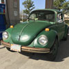
| That's my 68 bug !!!! |
|
| Back to top |
|
|
toddmin
Samba Member
Joined: September 28, 2015
Posts: 34
Location: Atlanta, GA, United States
|
| Posted: Fri Feb 26, 2016 10:48 am Post subject: Re: 1968 Type 1 - My First Resto |
|
|
| Wow, this is a great thread. Good job with all the work, pictures and documentation. |
|
| Back to top |
|
|
Cage44
Samba Member

Joined: January 16, 2012
Posts: 197
Location: Robinson Ranch, CA
|
| Posted: Sat Feb 27, 2016 9:44 pm Post subject: Re: 1968 Type 1 - My First Resto |
|
|
Thanks toddmin and Stephen B - Stephen your bug is looking great and your engine looks fantastic.
UPDATE: Trunk components.
With the interior near completion, I decided to move to the rest of the trunk parts that need attention. I have been driving the bug more and more each week, so I decided to get a spare tire and get the spare tire area in the trunk completed.
My original spare tire had a larger width rim (4.5j x15). It did not fit great in the spare tire well and it scratched the paint pretty good over the years. I always had to let a little air out so it would fit, which defeats the purpose. So, I tracked down a correct width (4J x 15) rim for my year at a salvage yard. That ½ inch should allow it to fit in the well much better. Also, the tire size was an issue. My old spare had 165s like the tires used on the car. I decided to go with a smaller width tire as well.
I purchased a Nankang 145R15 on Amazon. It was about 30 bucks more than I paid for my 165s but the reduced width should allow the spare to fit nice in the spare well. I assume this since it is a smaller width than the original tires which were roughly 155s.
I used the wire brush on my angle grinder to remove any surface rust and lose paint. The rim is in great shape with no bent lip or other damage. It took me a while to go through all the rims at the yard, because there were many in rough shape or with tons of rust. The one I bought had a tire on it, so that must have protected the middle of the rim the years it was sitting there.
Once I removed as much rust and loose paint, I degreased with simple green and cleaned everything up. I shot a coat of primer then painted both sides gloss black.
Next, I wanted to clean up and re-paint the access covers that are in the spare tire well. Here is a photo of them before I did anything.
During tear down, everything was labeled and the screws were taped to each applicable piece.
As a side note, it is nice to see the number parts boxes getting smaller as a pull out the original parts to prep for install. The covers are in great condition, just filthy with years and years of road grime. I used de-greaser and a small wire brush to remove all the grime. Once they were cleaned up, I used the wire wheel on the bench grinder to remove surface rust that was around a few of the edges.
One thing I have been using are cups to keep my screws in as I work on each piece. For the entire build, I try to put the screws or bolts used in the same holes I removed them from. Here, I am using Pringles cups that my kids used in their lunch which are perfect as a temporary holder as I work on things. The screws were placed in the same position as I placed the covers when I removed the marking tape.
I decided to strip the old paint off and get to bare metal with the hope for better paint results. Using a cheap brush, I put on paint stripper and waited a few minutes. The stripper acts fast and a lot of the paint came off as I was brushing the stripper on. This stuff (Jasco brand from Lowes) works great. I have been using this stuff for years on various projects and it eats the paint up quickly. After a few minutes, I just wiped most of the paint off with a paper towel. Some areas were a little stubborn, so I applied a second coat and used a small wire brush to remove the rest of the paint. Here is shot of the bare pieces.
With the paint removed, I sprayed on etching primer (since I was painting on bare metal) then put 2 coats of gloss black. Here are the finished covers.
I then installed the covers. No one is going to see them with the spare tire, but it just seemed right to make sure everything is cleaned up and repainted. Here is where they go.
With that completed, I put on a new hub cap for the spare and placed it in. With the smaller tire, it fits much better than I remember. Also, the 4 inch rim makes a big difference as well. I will likely place something behind the rim just to play it safe. Here are the final shots:
I decided to restore the jack. It worked fine, just did not feel right putting it in the car without taking it apart, cleaning it and painting what needs to be done. I already started and will update with a step by step once I am finished and figure it all out. Stay tuned
_________________
'68 Bug
Build thread http://www.thesamba.com/vw/forum/viewtopic.php?t=5...p;start=20 |
|
| Back to top |
|
|
Beetlebaum
Samba Member
Joined: December 04, 2008
Posts: 2181
Location: Virginia Beach, VA
|
|
| Back to top |
|
|
Cage44
Samba Member
Joined: January 16, 2012
Posts: 197
Location: Robinson Ranch, CA
|
| Posted: Thu Mar 03, 2016 9:25 pm Post subject: Re: 1968 Type 1 - My First Resto |
|
|
Bettlebaum - thanks! I can confirm, going with the 4j x15 rim with the 145 tire makes a huge difference for the spare tire well and will not compromise safety if the spare is needed. My old spare was the only rim that was 4.5j x 15 along with a 165 tire and that thing would not fit at all. Glad I switched it up and suggest others do the same if the spare fits too tight.
_________________
'68 Bug
Build thread http://www.thesamba.com/vw/forum/viewtopic.php?t=5...p;start=20 |
|
| Back to top |
|
|
shealray
Samba Member
Joined: February 28, 2016
Posts: 7
|
| Posted: Tue Mar 08, 2016 8:30 am Post subject: |
|
|
| Cage44 wrote: |
UPDATE.....
I cannot believe it has been 3 months already, but I finally am ready for body work and paint. The car is stripped, the body is detached (all bolts removed) and ready to be taken off, and the paint has been removed. Just trying to find a body and paint shop that can work with 4k to do the work. With the estimates I am receiving (12k - 20k) I may have to do it myself. I would rather leave it to the experts. However, I think there is a member that may be able to help out.
So, thanks to the community for your direct and indirect help and for giving folks like my the guts to take on a project like this. Updated pictures below...
|
I am in the process of striping off old layers of paint from my 1971 bug. What did you use to strip paint with and what did you use to get into the cracks? THANKS |
|
| Back to top |
|
|
Cage44
Samba Member
Joined: January 16, 2012
Posts: 197
Location: Robinson Ranch, CA
|
| Posted: Tue Mar 08, 2016 11:44 am Post subject: Re: 1968 Type 1 - My First Resto |
|
|
shealray - I used an angle grinder with a stripping disc and a wire wheel (NOT the braided kind of wire wheel). I purchased the strip disc from a vendor at a local car and VW show and swap meet. The disc is NOT made of strips of sandpaper. Here are pictures that explain better than I could:
Underside
Top
The strip disc was easy to use. I applied very little pressure and let the disc do the work. I also moved constantly so no one area what heat up too much and warp the metal. I would strip for a second or two then move a few feet away to another part, then repeat. Since the disc is non woven material, it seemed to dissipate heat as well. I must say, it worked very, very well.
As for the tight areas, I used the wire wheel on the angle grinder.
In retrospect, I think I would have tried chemical paint stripper. That would have taken much longer but would work great in the tight areas or even on the main body. I went the strip disc route since I had at least 3-4 coats of paint (all different colors).
As a side note, I tried the similar type of stripper that attaches to a drill, but it hardly did anything to remove the paint. The strip disc works fantastic.
I happen to be home today and was able to find my receipt. I ordered the discs from www.roarksupply.com. Here is the link:
http://www.roarksupply.com/product-p/4.5cleanstrip.htm
However, here is an amazon link which looks like the same or similar disc:
http://www.amazon.com/Paint-Rust-Stripping-Cup-Wheel/dp/B008GS91TE
Hope it helps!
_________________
'68 Bug
Build thread http://www.thesamba.com/vw/forum/viewtopic.php?t=5...p;start=20 |
|
| Back to top |
|
|
Cage44
Samba Member
Joined: January 16, 2012
Posts: 197
Location: Robinson Ranch, CA
|
| Posted: Sat Mar 19, 2016 8:37 am Post subject: Re: 1968 Type 1 - My First Resto |
|
|
UPDATE: Jack restore, jack restoration; jack tear down and rebuild.
First, I made sure I had the correct jack for my year and I do the jack was used for 1965 to 1969. I never changed the jack or altered it in any way, but since I have not owed the bug for its entire life, I wanted to make sure.
Here are a few before shots of the jack. I took a lot of pictures from various angles to make sure I put all the components back in the correct direction and the correct order.
Once I was comfortable that I had enough pictures, I started the tear down. There is a c clip at one end that keeps the jack mechanism from sliding off of the jack. I removed that first with a small screwdriver and a pair of pliers.
With the clip removed, I used a hammer to lightly push the mechanism up the jack post until it was off. I suggest that you DO NOT do this and use the jack handle as much as you can then use the hammer. I did not ruin anything, but after going through this, I should have used the design of the jack which would have made the removal step much easier with a lot less hammer strikes.
The entire mechanism stayed intact once it was off of the bar surprised me a little. I was not sure how much tension the springs were on, so I immediately put some safety glasses on just in case
I suggest you do the same.
I carefully, removed the longer spring and laid the pieces out in the order they were on the jack post.
Here is a picture of the springs and they are clearly different. To keep things in order, I used my parts cups and placed the springs in the position I took them off.
With the pieces apart, I started on the jack handle (the long piece that inserts into the jack mechanism to make it go up and down). I used the wire wheel on the bench grinder and removed all the rust and grit. It was not that bad but needed a clean up before painting. Here is a before and after clean up. I painted the jack handle gloss black.
For the jack and the mechanism, I cleaned all the pieces with degreaser and a wire brush. I then removed any remaining surface rust with the wire wheel on the grinder. Here are the parts all cleaned up.
There is a cup piece that is connected via a thick rivet/rod which accepts the jack handle. I decided to remove it for paint to match the other pieces. I used a small punch and a hammer to push the rivet/ rod out of the large part of the jack that goes into the jack points on the bug. Here are a few shots.
With all the pieces apart, I sprayed the large part of the jack with gloss black.
For the other pieces (not the springs) I used etching primer then painted them a gloss dark grey.
With the other pieces done, I moved on to the jack rod itself. I used the wire wheel and removed all the surface rust from the jack rod. I then used very fine steel wool to polish as best I could. I intend to make the jack functional so I did not paint the rod itself.
With the rod all cleaned up, I painted the bottom cup part of the jack rod. I went to Lowes, Ace Hardware, Home Depot and finally an auto parts store. I took the jack rod with me to try to find the closest match to the original color that was still present on the jack cup. Lowes and Ace did not have anything close. Home Depot had a color (which I bought) that was close but was still a little light. I decided to check an auto parts store and found the closest match by far.
I ended up using Dupli-Color DE1621 Old Ford Blue - Engine Enamel with Ceramic. Using the cap on the spray can it was the closest match. I taped up the bottom and top of the jack post where it inserts into the bottom cup and covered the entire post with newspaper. Here is the painted cup. It looks lighter than it is due to the flash, so I also took a photo without the flash on.
With all parts cleaned up and painted, it is time for reassembly. The good thing about the parts is all of them seem to have a bend or a little bump on one side which helps to reinstall them correctly. Since the pieces have to slide over the jack rod, I worked from the bottom up. Here are the pieces in the order the jack rod will slip through them. I used my jack handle first to make sure I had the correct orientation compared to the pictures I took prior to disassembly. Here are a few shots of just the pieces and the way they look and bend. They are in the correct orientation and will slide onto the jack rod the same direction.
Here are all of the pieces with the springs in place for the correct order to re-install.
With the order ready to go, I reattached the top cup by using the rivet/rod that keeps it in place.
I slid the jack rod from the bottom about an inch into the bottom hole of the large jack piece (painted gloss black). Once there was enough rod through the hole, I attached the first spring (the shorter thicker spring) and the first metal piece in place.
I then pushed the jack rod a little further through the pieces.
Once there was enough rod exposed, I installed the next metal piece then the remaining spring.
I pushed the jack rod further into the jack pieces with just enough room to compress the spring and install the final metal piece
the piece with the roller on it that touches the cup that was attached via the rivet/bolt. I then used the jack handle to lower the jack mechanism down the jack rod to give me enough room to install the c retaining clip.
With all parts installed, I worked the jack mechanism up and down the jack rod a few times and everything seemed to function just fine. I will test it this weekend, but I am confident that it will work. Here are a few shots of the finished and restored jack and jack handle.
_________________
'68 Bug
Build thread http://www.thesamba.com/vw/forum/viewtopic.php?t=5...p;start=20 |
|
| Back to top |
|
|
Stephen B
Samba Member
Joined: November 03, 2013
Posts: 53
Location: Victoria, BC, Canada
|
| Posted: Tue Mar 22, 2016 1:31 am Post subject: Re: 1968 Type 1 - My First Resto |
|
|
Great job on the rim, spare tire, and jack. Way too funny. I have also just finished the paint on my rims just this weekend. Here is a shot of them. Also today I have been down to the tire store looking for a tire that would fit better in the spare spot under the front hood. I also had a 165 r 15 on the four tires, and wanted to go smaller on the spare. I will follow your lead and go with a 145r15.
|
|
| Back to top |
|
|
Cage44
Samba Member
Joined: January 16, 2012
Posts: 197
Location: Robinson Ranch, CA
|
| Posted: Tue May 10, 2016 5:00 pm Post subject: Re: 1968 Type 1 - My First Resto |
|
|
UPDATE: Fuel hoses gas filler to gas tank and other parts; trunk spring covers; fuel gauge, vibrator and sending unit test.
It has been awhile since my last update. Frankly, I have bene doing what I should do and that is driving the bug as often as I can. Although there are still many small things to do, I took some time off to just enjoy the ride.
With the increase in driving I noticed a gas smell that would enter the cabin and also my fuel gauge was not working. The gauge did not work during my install and put that off as a Day 2 item. With my driving frequency increasing I decided to tackle that as well to see what is needed.
Here is a photo of the filler hoses.
One of the larger hoses was a little damp and I could smell gas on my fingers so I decided to replace both of them. I think this is another lesson learned. I purchased new hoses previously as well as new rubber sleeves that go on the metal pieces (filler, metal hose, tank intake). I decided to use the older ones because they looked like they were operational and intact. Although, it was nice having the original look of the hoses, after 40+ years they are going to fail.
I loosened the clamps that hold the metal middle part of the assembly and removed it. I then removed the remaining rubber hoses and left the rubber sleeves on since they are new and are working properly.
Here are the pieces apart and on the bench. The metal middle hose has a slight bend to it.
After inspecting the hoses, there were cracks on the inside which was leaking some of the gas and likely produced the smell.
I purchased replacement hoses from Wolfsburg West.
They needed to be cut to size. I just lined up the new hose next to the old one and cut as needed.
The clamps are still good as well, so I reused those and re-installed the hoses. I installed the hose that attaches to the gas filler in the body. I then installed the hose to the gas tank and lastly worked the metal middle part of the assembly into both hoses and lined everything up. Next, I clamped everything down.
Attached to the filler tube and the gas tank is a smaller hose and elbow that attaches to a T breather tube. I located the hose that attaches to the small tip of the T and installed that. I did not have the small hose on the T, it was covered with tape; another likely source for the gas smell. I used the tape since I was just driving around the block a few times. With my trips now at 20 to 30 minutes at a time, I knew it was time to get everything installed. Here is a photo of the T.
The longer thinner breather hose connects to the T and then goes up towards the cabin, around the fixed bolts for the nuts that would hold a wiring cover then down the left side of the trunk (driver side) to a factory pre-drilled hole just after the gas tank. Now, I am not sure how far up the long breather hose should go, I used my pre-tear down pictures to re-route the hose the same way it was before I removed it years ago.
With the full system installed, I wanted to install the hood lid spring covers, since the breather hose from the T ran close to the passenger side spring.
I cleaned the covers up and installed them over the springs. The cover has a slit that goes the length of the cover so you can simply open up the cover and push it over the spring.
Fuel gauge. I was not sure if it was the wiring, fuel tank sending unit, fuel gauge or the vibrator that is next to the gauge or a combination of the above.
First, I pulled out my digital multimeter in case I needed it. I must say, that anyone working on cars should invest in one
it can save a lot of time and headaches and I have used it frequently during the build as well as for maintenance and other testing needs. Also, buy or make some a few test leads with alligator clips
they come in real handy for testing as well. The meter I purchased came with alligator clips that I could simply attach to the existing probe. I made a few test leads with thicker wire and attached alligator clips
again, real handy when needed. See below:
First, after much research on this site, I started with the wire that goes from the gauge to the sending unit.
With the KEY OFF I removed the wire end on the sending unit. Take that end of the wire and ground it while also looking at the fuel gauge. Here is where the extra test lead comes in handy. I am working by myself so I used my test lead. I attached the test lead which allowed me to clip one end to the sending unit wire and the other to KNOWN ground something that has bare metal and is verified. I used the same fender bolt during the wiring harness install so I used that again.
I sat in the bug and turned on the key. The fuel gauge (which did nothing before) moved all the way up to fill THEN I QUICKLY TURNED THE KEY OFF so I did not burn up the gauge. This likely means that the fuel gauge is good and the sending unit may be bad. I decided to test more before buying anything or assuming I solved the problem. The sending unit could be working but I have a ground problem. Or there could be something with the vibrator next to the fuel gauge. I decided to test the vibrator next just to rule things out. First, I used the meter to test the voltage.
There is one wire that connects to the vibrator and the fuse block. With the key on, I tested the voltage going into the vibrator
it registered 12v. I then tested the voltage where the vibrator connects just to the left of the fuel gauge. The voltage was fluctuating up and down at a constant rate. Although there could be an issue with it, it seemed to function properly. The voltage should fluctuate and should not be zero or a fixed amount. That left the sending unit.
Since the gauge worked when I touched it to ground, I thought maybe I have a ground issue. So, I clipped my test lead to one of the screws on the sending unit and clipped the other end to a ground.
I then turned on the key and nothing happened
the fuel gauge did not move. So, time to take the sending unit out for testing. I pulled out the unit and was going to test the ohms using the meter. In lieu of this, I decided to again, attach a ground wire to the metal round body of the sending unit where the screw holes are. I left all wires attached.
I was able to hold the sending unit in one hand and reach in to turn the key on with the other. As I manually moved the sending unit float, the gauge started moving as well
slowly. I moved the float to the full position and the gauge slowly went to full. I stopped the float towards the middle and then the empty side and the gauge worked perfect. Now I know it is not the sending unit itself and I definitely have a ground problem with the sending unit. As a side note, the gauge will move much slower than the rate at which you move the float...this is by design.
I decided to take the screws that mount the sending unit to the gas tank and screw them in and out of each hole a few times. I noticed that there was a little black stuff coming out of the screw hole as I did this. LIKELY THE PAINT FROM THE NEW TANK!!!! I cleaned up each screw hole wiping away any paint that came up and re-installed the sending unit. IT WORKS!
So, I learned a lot and I am thankful that I now know how to troubleshoot the whole system. Another lesson learned that sometimes the simplest solution is the best and correct one.
One great thing as well, is the seal I bought for the sending unit was already breaking down, so I purchased another one that seems to be much better. More to come.
_________________
'68 Bug
Build thread http://www.thesamba.com/vw/forum/viewtopic.php?t=5...p;start=20 |
|
| Back to top |
|
|
Cage44
Samba Member
Joined: January 16, 2012
Posts: 197
Location: Robinson Ranch, CA
|
| Posted: Wed Jun 22, 2016 8:11 pm Post subject: Re: 1968 Type 1 - My First Resto |
|
|
UPDATE: SPEEDOMETER assembly Part 1.
I tore down the speedo to replace the gels for the turn signal, high beam, etc., reset the mileage, general clean up and re-lube the gears.
To play it safe, I picked up a donor 68 speedo from a wrecking yard in case I broke anything along the way or noticed that anything was broken. The speedo worked fine before I started working but, I thought I would like to have parts on hand just in case. I used the needle since my original needle was broken years ago. I also purchased 2 needles on-line, but decided to go with the donor one. Here is the donor speedo (dated November 1967):
Here is my speedo before I started the tear down (dated June 1968)
For some reason my glass and chrome ring were not crimped on, so it was easy to remove. I must have left it that way a few decades ago when I swapped out the speedo (sometime in the late 80s); at the same time I broke the needle but did not have the bread to replace it. Here is a shot with the glass removed:
As I read on other posts, I placed a mark on the metal housing where the needle pointed. I held the speedo as level as possible (not tilted up or down) and used a ruler to line up the needle and the metal rim since my needle was broken. The needle shaft has a spring underneath that provides some pre-tension before the needle rests on the face post. Again, with mine broken, it was tough to line up, but the ruler helped. If my needle was full length, I would have removed the 2 screws that hold the face on which would allow the face to rotate counterclockwise and the needle would fall freely so the mark can be made. That is a much safer approach then lifting the needle over the post on the face these needles are brittle after 40+ years of use. Here is a shot of the line:
With the mark made, time for tear down. First, I removed the fuel vibrator which is attached to the speedo with one screw. The vibrator attaches to the fuel gauge.
Next, the fuel gauge. The gauge is attached with two screws (circled in red below). I took a photo of the gauge with the markings in case I needed to replace it in the future that way I can purchase it without tearing things apart first.
Once the screws are removed, the gauge will slide out. Remove it carefully. I messed the gauge needle up a little when I replaced it decades ago but it works so I did not replace it at this time.
Next, remove the speedo cluster from the housing. The cluster is attached with 2 screws (marked in red below). I removed the screws which allowed the cluster to move. I could not get it out of the housing, the post where the speedo cable attaches just would not clear the hole so I could remove it. In order to provide more play, I removed the 2 screws that attach the face to the cluster and that allowed enough play to remove the cluster from the housing. DO NOT FORCE ANYTHING, TAKE IT SLOW. I just use a minor wiggle, wiggle technique to see how things move and work so no unneeded force is applied which could cause damage.
Here is a shot with the cluster removed. Once it was out of the housing, I immediately re-attached the face so it did not flop around or have any opportunity to get bent.
With the cluster out, I can now see the gels. For my year, the gels rest in a rubber holder that simply slides over plastic pieces in the housing. It makes things easy to repair. Here are a few shots:
I also made a quick diagram to make sure I put the correct gel colors in so everything is correct.
With all pieces apart, I cleaned up the inside and outside of the housing. Here is a before and after:
I purchased a gel replacement set from Wolfsburg West which had the green, red and blue gels that can be cut to fit in the rubber holders. The gel pieces have a smooth side and a side that is a little rough which is likely used to diffuse the light. When I installed them, I just made sure the rougher side faced out. Not sure the right way, but I did not want them to be different while looking from the drivers seat.
The original gels were much thicker. The round green gel and the round red gel were still a little pliable and did not break when they were removed. I removed the gels using a pair of tweezers. The gel for the turn signal pretty much disintegrated. I used the old gels as a template to cut out the new gels.
As a side note, the rubber holders have a notch that the gels are supposed to slide into. You can see it in the picture below:
Since the turn signal gel was toast and could not be used as a template, I had to just eyeball and cut then fit, cut then fit, etc., until the green center gel would fit in the rubber holder.
With everything cut and in the rubber holder, I re-installed the holder by slipping it over the plastic piece that holds it. I then shined a light from behind, here is the final look:
Now on to the cluster. There is a rod that holds the numbered gears in place and keeps everything working. The rod slides either left or right. Using needle nosed, pliers, I put one end of the plier on the rod end and the other next to the metal housing the rod goes through and squeezed lightly until the rod moved through the hole and was free on that side. I took it real slow and easy since I had no idea if the gears or numbered gear pieces would go flying. Here is a shot of the rod pushed in on one side.
With the rod pushed in, I was able to lift the rod up slightly which allowed the numbered gears to spin freely. Be patient and do not rush it. It took a few tries to get them to go to near zero. I would get them set then as a rotated the cluster the numbered pieces would spin and then I had to start over. Also, one would not seat right, so I would have to make sure it was good before I proceeded. As an example, here is a shot of one of the numbered clusters (the middle one) moving after I had to set and before I could put the rod back in.
Now, the rod holds 5 little gears that move the numbered gears that show the mileage. The rod gears have 2 different sized teeth. One is long and one is short. The long one is the width of the gear and the small one is about 2/3 of the distance. It is obvious that they are different. These gears need to be lined up the same so the small ones or long ones are all in the same spot. Meaning, when the rod is reinstalled, you should be able to see that the small teeth on each gear are lined up. I noticed when trying to get the rod back in place, if one of these guys were off, I could not sit the rod and the gears down onto the numbered gears. Here is a photo of the rod reinstalled and the gear difference:
As a side note, I DID NOT REMOVE THE ROD COMPLETELY. I just slid it over and lifted it up gently so I could spin 4 out of the 5 gears. I was left with the first numbered gear with a 1. So mileage reset to 00001.
I will update with the rest of the re-assembly and install soon.
_________________
'68 Bug
Build thread http://www.thesamba.com/vw/forum/viewtopic.php?t=5...p;start=20 |
|
| Back to top |
|
|
Beetlebaum
Samba Member
Joined: December 04, 2008
Posts: 2181
Location: Virginia Beach, VA
|
|
| Back to top |
|
|
Cage44
Samba Member
Joined: January 16, 2012
Posts: 197
Location: Robinson Ranch, CA
|
| Posted: Tue Jun 28, 2016 10:35 pm Post subject: Re: 1968 Type 1 - My First Resto |
|
|
Thanks Beetlebaum, I am very happy with the finished speedo...last picture in this post.
UPDATE: SPEEDOMETER assembly Part 2.
I tore down the speedo to replace the gels for the turn signal, high beam, etc., reset the mileage, general clean up and re-lube the gears.
With the gears lined up and the rod re-installed, I removed the old crusty grease and lubed the white/yellow gears with white lithium grease. I used the end of a Q tip, inserted it where the speedo cable goes and gently and slowly turned the gears to make sure everything appeared to work and the grease was distributed.
I then reversed my steps and began to re-install the assembly. I started with the cluster and re-installed it into the housing.
With the cluster installed, I moved on to the needle I took from the donor speedo. I cleaned it up gently then painted it white.
With the cluster installed, I kept the speedo face loose so I could re-install the needle and minimize any chance of breaking the needle. Before installing the needle, I made sure that the speedo face was turned counterclockwise so I did not have to lift the needle over the needle stop once installed. Using the needle mark on the housing, I pushed the needle on and lined it up so it would have the same pre-tension before I took things apart. Once the needle was installed, I lined up the face which, in turn, moves the speedo clock wise to create the tension it needs when resting on the stop. I then installed the 2 screws that hold the face on.
I then installed the fuel gauge and the vibrator in their original spots.
With the speedo cluster and other parts installed, I decided to paint the ring that goes next to the glass. The ring did not come out easily. I needed to open up the chrome ring a little more and I did not want to bend it too much or create a lot of dimples while trying to pry it open. So, I ended up using the rounded edge of a letter opener that had the same contour of the chrome ring. I just tapped and tapped around slowly and patiently until the chrome ring opened enough to remove the ring.
I stripped the ring down to bare metal, applied an etching primer, regular primer than a coat of paint to match the other interior pieces (stickshift, dash grills, e-brake handle, etc.)
Chrome ring. The chrome ring was a little crusty and had the original seal which was rock hard and missing many pieces. Here is the before picture:
I used a small screwdriver and a pick to remove the old seal. Again, took it slow and easy and just kept working it until all of the seal was off.
I then used degreaser and very fine wood finishing steel wool to remove any remaining crust and it brought out a great chrome shine. I also cleaned the glass. As a side note, I left the glass in the whole time. My thought was that way It would act as a barrier as I opened up the chrome ring and to help make sure the chrome ring had support. I wanted to prevent any accidental bends or any force that would misshape the chrome ring. Keeping the glass worked well for me.
Here is a shot of the chrome ring, glass and painted ring installed.
I reinstalled the chrome ring, glass and inside ring, then tapped the chrome ring in a few spots until it was secure against the speedo assembly. Here is the finished speedo not perfect, but nice, clean and looks freshened up:
Before I install the speedo in the dash, I needed to install a new chrome speedo dash ring. I broke the tabs off of my original one, so I purchased a new one.
I installed the chrome dash ring and made sure it seated as far in as possible and to make sure the ring sat flush against the dash.
I also purchased a speedo seal where the speedo touches the inside part of the opening from the trunk. It fits nicely around the speedo chrome ring.
Here is a shot of the finished speedo in the dash with the indicator lights lit up where possible.
_________________
'68 Bug
Build thread http://www.thesamba.com/vw/forum/viewtopic.php?t=5...p;start=20 |
|
| Back to top |
|
|
coxbzh
Samba Member
Joined: March 01, 2016
Posts: 22
Location: Brest meme
|
| Posted: Wed Jun 29, 2016 4:40 am Post subject: Re: 1968 Type 1 - My First Resto |
|
|
Congratulations Cage44 .
Your post is a significant wealth of information for me.
You did a great job with a lot of photo and tricks that will help me
thank you |
|
| Back to top |
|
|
Chochobeef
Samba Member
Joined: May 01, 2013
Posts: 811
Location: Ft. Worth, Texas
|
| Posted: Wed Jun 29, 2016 6:13 am Post subject: Re: 1968 Type 1 - My First Resto |
|
|
| Nice job on your speedo. Everything is coming along nicely. |
|
| Back to top |
|
|
Cage44
Samba Member
Joined: January 16, 2012
Posts: 197
Location: Robinson Ranch, CA
|
| Posted: Fri Jul 15, 2016 6:13 pm Post subject: Re: 1968 Type 1 - My First Resto |
|
|
Coxbzh thanks and I am glad I could provide some help.
Chochobeef thanks, I getting very close to wrapping this up.
UPDATE: Trunk Fresh Air Hoses, Defrost Hoses
With the speedo installed and working, it is time to install the fresh air and defrost hoses. I had the original defrost hoses (the short hoses that connect to the each side of the windshield, just pass the hood brackets and springs). See picture below it is the larger diameter connection:
The new hose had to be cut down since it was supplied as 1 long piece.
Using a blade, I decided to cut the new paper hose slightly longer than the original so that I cut trim it down a little at a time until it fits. I cut both the driver side and passenger side the same length to start.
Once I found the proper hose length, I slide the new paper hose onto the bottom connection then connected the other end to the metal connection at the top near the edge of the windshield.
Here is the driver side hose installed.
Next, I installed the defrost hoses (may be called pre-heat hoses) that connect to the center vent in the dash. These hoses are plastic and my original hoses are in good shape so I re-used them. During tear down, I labeled everything which makes reassembly much easier.
I cleaned up each hose removing old dust and other grit then installed the passenger side first. One end of the hose goes to the other part of the Y connection near the top corner of the trunk
same Y connection where the defrost hose connects to. The other end of the hose connects to the center vents on the dash board. Here are shots of the passenger side hose:
Here is the top connection, just past the wiper motor assembly and just above the stereo:
Here is the bottom connection, where it connects to the Y.
Once connected, the hose runs in front of the glove box when facing the trunk.
The driver side was a little more difficult to get to since there are more things in the way. The top connection will connect to the center vent (driver side) in the dash then to the Y on the driver side.
Next I installed the fresh air duct that will connect to the remaining dash vents and ultimately to the plenum chamber that sits directly under the hood cut outs above the VW emblem.
Here is a shot of the original plastic ducts and the part number for one of them:
The ducts connect to the dash vents, one on the passenger side and one on the driver side. They simply push and clip onto the bottom of the dash vents.
Here is the passenger one installed:
Here is a picture of the bottom of the driver side dash vent and the duct installed:
Here are both ducts installed and waiting for the plenum chamber - fresh air box.
I will update with pictures of the plenum chamber - fresh air box - and other parts needed for the installation.
_________________
'68 Bug
Build thread http://www.thesamba.com/vw/forum/viewtopic.php?t=5...p;start=20 |
|
| Back to top |
|
|
Cage44
Samba Member
Joined: January 16, 2012
Posts: 197
Location: Robinson Ranch, CA
|
| Posted: Tue Jul 19, 2016 8:02 pm Post subject: Re: 1968 Type 1 - My First Resto |
|
|
UPDATE: Fresh Air Box / Fresh Air Control Box
With the fresh air hoses and defrost hoses in place, it was time to install the Fresh Air Box and the mechanism that controls the air flaps in the box which has posts that go through the dash to the cabin.
I cleaned up the fresh air box and the adjusting knob mechanism. Being inside the trunk it was not very dirty. I had very little lubrication on the gears, so I made a note to clean up what was there and lube it before re-installation. Here are a few shots of the assembly before and after it was cleaned up.
Here are a few close ups of the gear assemblies:
Interesting how the long plastic piece that the gear connects to has different size teeth, they have different depths:
Since the cables are moved by the gears that then open and close the flaps to the fresh air box, I used steel wool on the cables and sprayed lubricant down each cable sleeve until the cables moved smoothly and the flaps as well. Here is a photo of one flap open and closed.
I used white lithium grease for each gear and twisted the knobs back and forth to distribute the grease.
Once everything was lubed up, time to install the gear assembly. I could not install it with the ash tray installed so I removed the ash tray. Once that was out of the way, I was able to work the gear assembly in its place. The two knob rods need to go through the dash holes where you control the flaps from inside the cabin. It was a little tricky since there is not much space, but you know when it fits. DO NOT FORCE ANYTHING. I would get one knob inserted but the other side would not go in, or vice versa. Once it is lined up it will slide in and allow you to bolt it down. The space is tight, but the assembly bolts in two places, with a bolt on the left side and a bolt on the right. Here are a few shots of the placement and where the assembly bolts onto the body. Once bolted in, I was able to re-install the ashtray.
With the assembly in place, I could now complete the last set of dash knobs for the interior. The knobs are easy to identify since they have square openings to go over the gear assembly shafts. Here is a host before I cleaned them up.
I purchased new knob inserts and simply slipped them into the rubber knob.
Here is the center part of the dash with all knobs installed and working.
Next the glove box. My original box was beat badly. The edges are all frayed from the many times in high school I had to remove it to unlock the doors since I locked my keys in the bug.
I purchased a new box and installed it next. The box is held by a metal strap that screws in place right under the glove box. I used nylon washer so no paint was scratched. Once installed, the hose is placed just inside the bracket where the dash wiring cover is installed.
Next, the fresh air box. The box attaches right at the top of the trunk, and slides under the lip where the 3 screw holes are. My old screws were rusty and the washers were different sizes. I used new stainless steel screws and nylon washers.
I purchased new paper hoses for the ends of the fresh air chamber where it connects to the plastic hoses that connect to the dash vents. They were a little long, so I had to cut them a little. I measured and cut each side separately just in case they were different sizes
I did not want to short it.
There are a few final steps to complete the trunk
stay tuned.
_________________
'68 Bug
Build thread http://www.thesamba.com/vw/forum/viewtopic.php?t=5...p;start=20 |
|
| Back to top |
|
|
Cage44
Samba Member
Joined: January 16, 2012
Posts: 197
Location: Robinson Ranch, CA
|
| Posted: Sun Jul 24, 2016 7:35 pm Post subject: Re: 1968 Type 1 - My First Resto |
|
|
UPDATE: Fresh Air Box / Fresh Air Control Box and related items.
With the fresh air box installed, time for the finishing touches. First, I started with the fresh air box drain tube. I used my original since it was not cracked. I cleaned it up and slipped it onto the bottom drain of the fresh air box.
I had stereo wires going down the same path that the fresh air box drain tube goes, so I decided to use some left over cable wrap to tidy things up. I just cut it to size then installed.
Now for the drain tube. I had a metal pipe that was used when I bought the car decades ago, so I decided to replace it with a paper drain tube to match everything else. The tube came a tad too long so I did cut a little off one end. The tube goes from the bottom of the drain tube in the fresh air box, and then inserts into the opening about 14 inches below the tube and enters through a hole that allows the water to drain out to the front of the car, past the firewall. When you ever replace this, make sure the tube goes through that hole and not just into the opening or you could get water in unwanted places. My stereo wires enter the cabin from the same area, so it was important that I make sure the drain tube goes through the hole past the firewall.
Next, I installed the wiring cover using 2 knurled nuts. Mine were in great shape so I just cleaned them up and secured the wiring cover. Finally, I bought a new seal for the fresh air box that goes on top to seal the hood opening when the hood is down. The seal has a groove and lip that rests right on top of the fresh air box. Not the best fit, but it does the job.
Here are a few final shots with everything installed. Not the cleanest but it covers most of the wiring rats nest and keeps things looking somewhat tidy and finished looking. Trunk is now complete.
_________________
'68 Bug
Build thread http://www.thesamba.com/vw/forum/viewtopic.php?t=5...p;start=20 |
|
| Back to top |
|
|
|


